Saturday, February 29, 2020

How to insert music in pendrive?

How to Put Music on a Flash Drive


You can use a USB flash drive to quickly transfer music files from one computer to another, save a backup of your music, or play music on devices that support a USB drive. This is great for sharing music with a friend, playing it on a stereo that supports USB, or just creating a backup. If your USB drive isn't working properly, you may need to reformat it.


Insert the USB drive into a USB port on your computer. Try to use a port directly on your computer. Avoid USB hubs, as these will lead to slower transfer speeds.
  • Windows will usually notify you that a USB drive was inserted, and an AutoPlay window may appear. You can close the AutoPlay window for now.
  • If this is your first time plugging the USB drive into the computer, Windows may install some drivers. This should only take a few moments.
  • A USB hub is an external device that allows you to plug multiple USB devices into a single USB port.

Open File Explorer 
Image titled WindowsFileExplorer.png
.
 It has an icon that resembles a folder with a blue clip on it. It's usually found in the task bar at the bottom of the screen.
  • Alternatively, you can right-click the Windows button and select "File Explorer," or


Click This PC. It's in the sidebar to the left in File Explorer. This displays all the drives connected to your PC.


Find your USB drive. Your USB drive will be displayed in the "Devices and drives" section of the window.
  • If you don't see your USB drive, check the Troubleshooting section at the end of this article.

Note the drive letter for the USB drive. You'll find this in parentheses next to the drive's label, e.g. "(E:)" or "(F:)." Knowing the drive letter will make it easier to send files to the drive later.

Check the amount of free space on the drive. The amount of space available will dictate the amount of music you can store on it. The amount of free space will be shown underneath the drive.
  • The average MP3 file will range from 3-5 MB in size or 1 MB per minute of audio, but this varies depending on the quality of each file. See the chart at the end of the article for a breakdown of the average number of songs you can fit.
  • You can quickly delete everything on the USB by right-clicking on it and selecting "Format." Start the format process and everything will be deleted from the drive.


Find the music files that you want to copy to the USB drive. Your music files may be located in a variety of locations on your computer:
  • Many programs store music files in your "Music" folder.
  • If you've downloaded music from a website, it will likely be in your "Downloads" folder.
  • In Windows Media Player, right-click on a music file in your library and select "Open file location" to open the folder containing that music file.
  • In iTunes, right-click on a track in your library and select "Show in Windows Explorer" to open the folder containing that song.
  • You can perform a Windows search for "MP3" to search for all of the MP3 files on your computer. Open the Start menu or screen and type "MP3" to begin searching.
Select all of the files and folders that you want to copy. You can send multiple files and folders to the USB drive at once. Click and drag a selection box, or hold Ctrl and click each item you want to select. You can also press Ctrl+A to select everything in the current folder.
  • Check the size of your selection by right-clicking it and selecting "Properties." Make sure that the size of your selection is smaller than the amount of free space on your USB drive.
  • You may find it easier to move all of your music files into one spot on your computer, organized into folders. You can then copy all of the folders and files at once.
right-click on your selection. This displays a menu next to the selected file(s).

  1. Hover over Send to. It's in the menu that appears when you right-click a selected file. This displays all your drives and some other options.
    • Alternatively, you can also click Copy in the menu that appears when you right-click a file.

Wednesday, February 26, 2020

Microprocessor - 8085 Pin Configuration

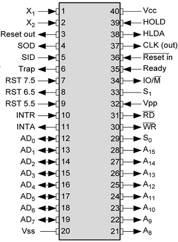
The following image depicts the pin diagram of 8085 Microprocessor −
8085 Pin Configuration
The pins of a 8085 microprocessor can be classified into seven groups −

Address bus

A15-A8, it carries the most significant 8-bits of memory/IO address.

Data bus

AD7-AD0, it carries the least significant 8-bit address and data bus.

Control and status signals

These signals are used to identify the nature of operation. There are 3 control signal and 3 status signals.
Three control signals are RD, WR & ALE.
  • RD − This signal indicates that the selected IO or memory device is to be read and is ready for accepting data available on the data bus.
  • WR − This signal indicates that the data on the data bus is to be written into a selected memory or IO location.
  • ALE − It is a positive going pulse generated when a new operation is started by the microprocessor. When the pulse goes high, it indicates address. When the pulse goes down it indicates data.
Three status signals are IO/M, S0 & S1.

IO/M

This signal is used to differentiate between IO and Memory operations, i.e. when it is high indicates IO operation and when it is low then it indicates memory operation.

S1 & S0

These signals are used to identify the type of current operation.

Power supply

There are 2 power supply signals − VCC & VSS. VCC indicates +5v power supply and VSS indicates ground signal.

Clock signals

There are 3 clock signals, i.e. X1, X2, CLK OUT.
  • X1, X2 − A crystal (RC, LC N/W) is connected at these two pins and is used to set frequency of the internal clock generator. This frequency is internally divided by 2.
  • CLK OUT − This signal is used as the system clock for devices connected with the microprocessor.

Interrupts & externally initiated signals

Interrupts are the signals generated by external devices to request the microprocessor to perform a task. There are 5 interrupt signals, i.e. TRAP, RST 7.5, RST 6.5, RST 5.5, and INTR. We will discuss interrupts in detail in interrupts section.
  • INTA − It is an interrupt acknowledgment signal.
  • RESET IN − This signal is used to reset the microprocessor by setting the program counter to zero.
  • RESET OUT − This signal is used to reset all the connected devices when the microprocessor is reset.
  • READY − This signal indicates that the device is ready to send or receive data. If READY is low, then the CPU has to wait for READY to go high.
  • HOLD − This signal indicates that another master is requesting the use of the address and data buses.
  • HLDA (HOLD Acknowledge) − It indicates that the CPU has received the HOLD request and it will relinquish the bus in the next clock cycle. HLDA is set to low after the HOLD signal is removed.

Serial I/O signals

There are 2 serial signals, i.e. SID and SOD and these signals are used for serial communication.
  • SOD (Serial output data line) − The output SOD is set/reset as specified by the SIM instruction.
  • SID (Serial input data line) − The data on this line is loaded into accumulator whenever a RIM instruction is executed.

Now let us discuss the addressing modes in 8085 Microprocessor.

Addressing Modes in 8085

These are the instructions used to transfer the data from one register to another register, from the memory to the register, and from the register to the memory without any alteration in the content. Addressing modes in 8085 is classified into 5 groups −

Immediate addressing mode

In this mode, the 8/16-bit data is specified in the instruction itself as one of its operand. For example: MVI K, 20F: means 20F is copied into register K.

Register addressing mode

In this mode, the data is copied from one register to another. For example: MOV K, B: means data in register B is copied to register K.

Direct addressing mode

In this mode, the data is directly copied from the given address to the register. For example: LDB 5000K: means the data at address 5000K is copied to register B.

Indirect addressing mode

In this mode, the data is transferred from one register to another by using the address pointed by the register. For example: MOV K, B: means data is transferred from the memory address pointed by the register to the register K.

Implied addressing mode

This mode doesn’t require any operand; the data is specified by the opcode itself. For example: CMP.

Interrupts in 8085

Interrupts are the signals generated by the external devices to request the microprocessor to perform a task. There are 5 interrupt signals, i.e. TRAP, RST 7.5, RST 6.5, RST 5.5, and INTR.
Interrupt are classified into following groups based on their parameter −
  • Vector interrupt − In this type of interrupt, the interrupt address is known to the processor. For example: RST7.5, RST6.5, RST5.5, TRAP.
  • Non-Vector interrupt − In this type of interrupt, the interrupt address is not known to the processor so, the interrupt address needs to be sent externally by the device to perform interrupts. For example: INTR.
  • Maskable interrupt − In this type of interrupt, we can disable the interrupt by writing some instructions into the program. For example: RST7.5, RST6.5, RST5.5.
  • Non-Maskable interrupt − In this type of interrupt, we cannot disable the interrupt by writing some instructions into the program. For example: TRAP.
  • Software interrupt − In this type of interrupt, the programmer has to add the instructions into the program to execute the interrupt. There are 8 software interrupts in 8085, i.e. RST0, RST1, RST2, RST3, RST4, RST5, RST6, and RST7.
  • Hardware interrupt − There are 5 interrupt pins in 8085 used as hardware interrupts, i.e. TRAP, RST7.5, RST6.5, RST5.5, INTA.
Note − NTA is not an interrupt, it is used by the microprocessor for sending acknowledgement. TRAP has the highest priority, then RST7.5 and so on.

Interrupt Service Routine (ISR)

A small program or a routine that when executed, services the corresponding interrupting source is called an ISR.

TRAP

It is a non-maskable interrupt, having the highest priority among all interrupts. Bydefault, it is enabled until it gets acknowledged. In case of failure, it executes as ISR and sends the data to backup memory. This interrupt transfers the control to the location 0024H.

RST7.5

It is a maskable interrupt, having the second highest priority among all interrupts. When this interrupt is executed, the processor saves the content of the PC register into the stack and branches to 003CH address.

RST 6.5

It is a maskable interrupt, having the third highest priority among all interrupts. When this interrupt is executed, the processor saves the content of the PC register into the stack and branches to 0034H address.

RST 5.5

It is a maskable interrupt. When this interrupt is executed, the processor saves the content of the PC register into the stack and branches to 002CH address.

INTR

It is a maskable interrupt, having the lowest priority among all interrupts. It can be disabled by resetting the microprocessor.
When INTR signal goes high, the following events can occur −
  • The microprocessor checks the status of INTR signal during the execution of each instruction.
  • When the INTR signal is high, then the microprocessor completes its current instruction and sends active low interrupt acknowledge signal.
  • When instructions are received, then the microprocessor saves the address of the next instruction on stack and executes the received instruction.
Let us take a look at the programming of 8085 Microprocessor.
Instruction sets are instruction codes to perform some task. It is classified into five categories.
S.No.Instruction & Description
1Control Instructions
Following is the table showing the list of Control instructions with their meanings.
2Logical Instructions
Following is the table showing the list of Logical instructions with their meanings.
3Branching Instructions
Following is the table showing the list of Branching instructions with their meanings.
4Arithmetic Instructions
Following is the table showing the list of Arithmetic instructions with their meanings.
5Data Transfer Instructions
Following is the table showing the list of Data-transfer instructions with their meanings.

8085 – Demo Programs

Now, let us take a look at some program demonstrations using the above instructions −

Adding Two 8-bit Numbers

Write a program to add data at 3005H & 3006H memory location and store the result at 3007H memory location.
Problem demo −
(3005H) = 14H 
   (3006H) = 89H
Result −
14H + 89H = 9DH
The program code can be written like this −
LXI H 3005H   : "HL points 3005H" 
MOV A, M      : "Getting first operand" 
INX H         : "HL points 3006H" 
ADD M         : "Add second operand" 
INX H         : "HL points 3007H" 
MOV M, A      : "Store result at 3007H" 
HLT           : "Exit program" 

Exchanging the Memory Locations

Write a program to exchange the data at 5000M& 6000M memory location.
LDA 5000M   : "Getting the contents at5000M location into accumulator" 
MOV B, A    : "Save the contents into B register" 
LDA 6000M   : "Getting the contents at 6000M location into accumulator" 
STA 5000M   : "Store the contents of accumulator at address 5000M" 
MOV A, B    : "Get the saved contents back into A register" 
STA 6000M   : "Store the contents of accumulator at address 6000M" 

Arrange Numbers in an Ascending Order

Write a program to arrange first 10 numbers from memory address 3000H in an ascending order.
MVI B, 09         :"Initialize counter"      
START             :"LXI H, 3000H: Initialize memory pointer" 
MVI C, 09H        :"Initialize counter 2" 
BACK: MOV A, M    :"Get the number" 
INX H             :"Increment memory pointer" 
CMP M             :"Compare number with next number" 
JC SKIP           :"If less, don’t interchange" 
JZ SKIP           :"If equal, don’t interchange" 
MOV D, M 
MOV M, A 
DCX H 
MOV M, D 
INX H             :"Interchange two numbers" 
SKIP:DCR C        :"Decrement counter 2" 
JNZ BACK          :"If not zero, repeat" 
DCR B             :"Decrement counter 1" 
JNZ START 
HLT               :"Terminate program execution" 

8086 Microprocessor is an enhanced version of 8085Microprocessor that was designed by Intel in 1976. It is a 16-bit Microprocessor having 20 address lines and16 data lines that provides up to 1MB storage. It consists of powerful instruction set, which provides operations like multiplication and division easily.
It supports two modes of operation, i.e. Maximum mode and Minimum mode. Maximum mode is suitable for system having multiple processors and Minimum mode is suitable for system having a single processor.

Features of 8086

The most prominent features of a 8086 microprocessor are as follows −
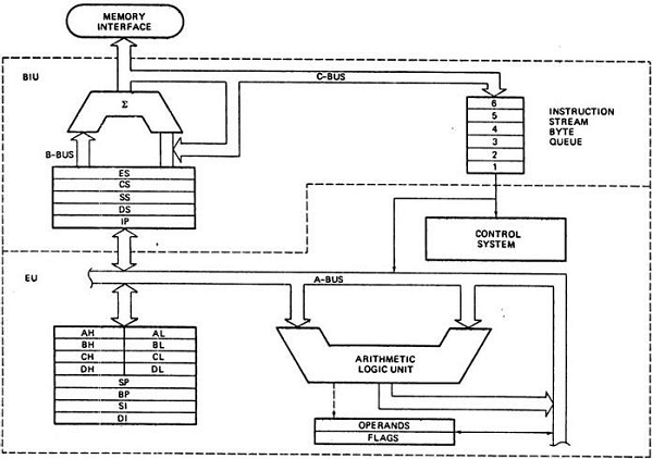
  • It has an instruction queue, which is capable of storing six instruction bytes from the memory resulting in faster processing.
  • It was the first 16-bit processor having 16-bit ALU, 16-bit registers, internal data bus, and 16-bit external data bus resulting in faster processing.
  • It is available in 3 versions based on the frequency of operation −
    • 8086 → 5MHz
    • 8086-2 → 8MHz
    • (c)8086-1 → 10 MHz
  • It uses two stages of pipelining, i.e. Fetch Stage and Execute Stage, which improves performance.
  • Fetch stage can prefetch up to 6 bytes of instructions and stores them in the queue.
  • Execute stage executes these instructions.
  • It has 256 vectored interrupts.
  • It consists of 29,000 transistors.

Comparison between 8085 & 8086 Microprocessor

  • Size − 8085 is 8-bit microprocessor, whereas 8086 is 16-bit microprocessor.
  • Address Bus − 8085 has 16-bit address bus while 8086 has 20-bit address bus.
  • Memory − 8085 can access up to 64Kb, whereas 8086 can access up to 1 Mb of memory.
  • Instruction − 8085 doesn’t have an instruction queue, whereas 8086 has an instruction queue.
  • Pipelining − 8085 doesn’t support a pipelined architecture while 8086 supports a pipelined architecture.
  • I/O − 8085 can address 2^8 = 256 I/O's, whereas 8086 can access 2^16 = 65,536 I/O's.
  • Cost − The cost of 8085 is low whereas that of 8086 is high.

Architecture of 8086

The following diagram depicts the architecture of a 8086 Microprocessor −
Architecture of 8086

A Multi-Protocol Infrared Remote Library for the Arduino

Do you want to control your Arduino with an IR remote? Do you want to use your Arduino to control your stereo or other devices? This IR remote library lets you both send and receive IR remote codes in multiple protocols. It supports NEC, Sony SIRC, Philips RC5, Philips RC6, and raw protocols. If you want additional protocols, they are straightforward to add. The library can even be used to record codes from your remote and re-transmit them, as a minimal universal remote.
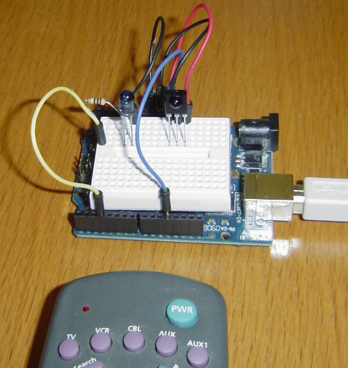
Arduino IR remote
To use the library, download from github and follow the installation instructions in the readme.

How to send

This infrared remote library consists of two parts: IRsend transmits IR remote packets, while IRrecv receives and decodes an IR message. IRsend uses an infrared LED connected to output pin 3. To send a message, call the send method for the desired protocol with the data to send and the number of bits to send. The examples/IRsendDemo sketch provides a simple example of how to send codes:
#include <IRremote.h>
IRsend irsend;

void setup()
{
  Serial.begin(9600);
}

void loop() {
  if (Serial.read() != -1) {
    for (int i = 0; i < 3; i++) {
      irsend.sendSony(0xa90, 12); // Sony TV power code
      delay(100);
    }
  }
} 
This sketch sends a Sony TV power on/off code whenever a character is sent to the serial port, allowing the Arduino to turn the TV on or off. (Note that Sony codes must be sent 3 times according to the protocol.)

How to receive

IRrecv uses an infrared detector connected to any digital input pin.
The examples/IRrecvDemo sketch provides a simple example of how to receive codes:
#include <IRremote.h>

int RECV_PIN = 11;
IRrecv irrecv(RECV_PIN);
decode_results results;

void setup()
{
  Serial.begin(9600);
  irrecv.enableIRIn(); // Start the receiver
}

void loop() {
  if (irrecv.decode(&results)) {
    Serial.println(results.value, HEX);
    irrecv.resume(); // Receive the next value
  }
}
The IRrecv class performs the decoding, and is initialized with enableIRIn(). The decode() method is called to see if a code has been received; if so, it returns a nonzero value and puts the results into the decode_results structure. (For details of this structure, see the examples/IRrecvDump sketch.) Once a code has been decoded, the resume() method must be called to resume receiving codes. Note that decode() does not block; the sketch can perform other operations while waiting for a code because the codes are received by an interrupt routine.

Hardware setup

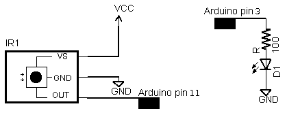
The library can use any of the digital input signals to receive the input from a 38KHz IR receiver module. It has been tested with the Radio Shack 276-640 IR receiver and the Panasonic PNA4602. Simply wire power to pin 1, ground to pin 2, and the pin 3 output to an Arduino digital input pin, e.g. 11. These receivers provide a filtered and demodulated inverted logic level output; you can't just use a photodiode or phototransistor. I have found these detectors have pretty good range and easily work across a room.
IR wiring
For output, connect an IR LED and appropriate resistor to PWM output pin 3. Make sure the polarity of the LED is correct, or it won't illuminate - the long lead is positive. I used a NTE 3027 LED (because that's what was handy) and 100 ohm resistor; the range is about 15 feet. For additional range, you can amplify the output with a transistor.

Some background on IR codes

An IR remote works by turning the LED on and off in a particular pattern. However, to prevent inteference from IR sources such as sunlight or lights, the LED is not turned on steadily, but is turned on and off at a modulation frequency (typically 36, 38, or 40KHz). The time when a modulated signal is being sent will be called a mark, and when the LED is off will be called a space.
Each key on the remote has a particular code (typically 12 to 32 bits) associated with it, and broadcasts this code when the key is pressed. If the key is held down, the remote usually repeatedly broadcasts the key code. For an NEC remote, a special repeat code is sent as the key is held down, rather than repeatedly sending the code. For Philips RC5 or RC6 remotes, a bit in the code is toggled each time a key is pressed; the receiver uses this toggle bit to determine when a key is pressed down a second time.
On the receiving end, the IR detector demodulates this signal, and outputs a logic-level signal indicating if it is receiving a signal or not. The IR detector will work best when its frequency matches the sender's frequency, but in practice it doesn't matter a whole lot.
The best source I've found for details on the various types of IR codes is SB IR knowledge base.

Handling raw codes

The library provides support for sending and receiving raw durations. This is intended mainly for debugging, but can also be used for protocols the library doesn't implement, or to provide universal remote functionality.
The raw data for received IR measures the duration of successive spaces and marks in 50us ticks. The first measurement is the gap, the space before the transmission starts. The last measurement is the final mark.
The raw data for sending IR holds the duration of successive marks and spaces in microseconds. The first value is the first mark, and the last value is the last mark.
There are two differences between the raw buffers for sending and for receiving. The send buffer values are in microseconds, while the receive buffer values are in 50 microsecond ticks. The send buffer starts with the duration of the first mark, while the receive buffer starts with the duration of the gap space before the first mark. The formats are different because I considered it useful for the library to measure gaps between transmissions, but not useful for the library to provide these gaps when transmitting. For receiving, 50us granularity is sufficient for decoding and avoids overflow of the gaps, while for transmitting, 50us granularity is more than 10% error so 1us granularity seemed better.

Obtaining codes for your remote

The easiest way to obtain codes to work with your device is to use this library to decode and print the codes from your existing remote.
Various libraries of codes are available online, often in proprietary formats. The Linux Infrared Remote Control project (LIRC), however, has an open format for describing codes for many remotes. Note that even if you can't find codes for your exact device model, a particular manufacturer will usually use the same codes for multiple products.
Beware that other sources may be inconsistent in how they handle these protocols, for instance reversing the order, flipping 1 and 0 bits, making start bits explicit, dropping leading or trailing bits, etc. In other words, if the IRremote library yields different codes than you find listed elsewhere, these inconsistencies are probably why.

Details of the receiving library

The IRrecv library consists of two parts. An interrupt routine is called every 50 microseconds, measures the length of the marks and spaces, and saves the durations in a buffer. The user calls a decoding routine to decode the buffered measurements into the code value that was sent (typically 11 to 32 bits).
The decode library tries decoding different protocols in succession, stopping if one succeeds. It returns a structure that contains the raw data, the decoded data, the number of bits in the decoded data, and the protocol used to decode the data.
For decoding, the MATCH macro determine if the measured mark or space time is approximately equal to the expected time.
The RC5/6 decoding is a bit different from the others because RC5/6 encode bits with mark + space or space + mark, rather than by durations of marks and spaces. The getRClevel helper method splits up the durations and gets the mark/space level of a single time interval.
For repeated transmissions (button held down), the decoding code will return the same decoded value over and over. The exception is NEC, which sends a special repeat code instead of repeating the transmission of the value. In this case, the decode routine returns a special REPEAT value.
In more detail, the receiver's interrupt code is called every time the TIMER1 overflows, which is set to happen after 50 microseconds. At each interrupt, the input status is checked and the timer counter is incremented. The interrupt routine times the durations of marks (receiving a modulated signal) and spaces (no signal received), and records the durations in a buffer. The first duration is the length of the gap before the transmission starts. This is followed by alternating mark and space measurements. All measurements are in "ticks" of 50 microseconds.
The interrupt routine is implemented as a state machine. It starts in STATE_IDLE, which waits for the gap to end. When a mark is received, it moves to STATE_MARK which times the duration of the mark. It then alternates between STATE_MARK and STATE_SPACE to time marks and spaces. When a space of sufficiently long duration is received, the state moves to STATE_STOP, indicating a full transmission is received. The interrupt routine continues to time the gap, but blocks in this state.
The STATE_STOP is used a a flag to indicate to the decode routine that a full transmission is available. When processing is done, the resume() method sets the state to STATE_IDLE so the interrupt routine can start recording the next transmission. There are a few things to note here. Gap timing continues during STATE_STOP and STATE_IDLE so an accurate measurement of the time between transmissions can be obtained. If resume() is not called before the next transmission starts, the partial transmission will be discarded. The motivation behind the stop/resume is to ensure the receive buffer is not overwritten while it is still being processed; debugging becomes very difficult if the buffer is constantly changing.

Details of the sending library

The transmission code is straightforward. To ensure accurate output frequencies and duty cycles, I use the PWM timer, rather than delay loops to modulate the output LED at the appropriate frequency. (See my Arduino PWM Secrets article for more details on the PWM timers.) At the low level, enableIROut sets up the timer for PWM output on pin 3 at the proper frequency. The mark() method sends a mark by enabling PWM output and delaying the specified time. The space() method sends a space by disabling PWM output and delaying the specified time.
The IRremote library treats the different protocols as follows:
NEC: 32 bits are transmitted, most-significant bit first. (protocol details)
Sony: 12 or more bits are transmitted, most-significant bit first. Typically 12 or 20 bits are used. Note that the official protocol is least-significant bit first. (protocol details) For more details, I've written an article that describes the Sony protocol in much more detail: Understanding Sony IR remote codes.
RC5: 12 or more bits are transmitted most-significant bit first. The message starts with the two start bits, which are not part of the code values. (protocol details)
RC6: 20 (typically) bits are transmitted, most-significant bit first. The message starts with a leader pulse, and a start bit, which is not part of the code values. The fourth bit is transmitted double-wide, since it is the trailer bit. (protocol details)
For Sony and RC5/6, each transmission must be repeated 3 times as specified in the protocol. The transmission code does not implement the RC5/6 toggle bit; that is up to the caller.

Adding new protocols

Manufacturers have implemented many more protocols than this library supports. Adding new protocols should be straightforward if you look at the existing library code. A few tips: It will be easier to work with a description of the protocol rather than trying to entirely reverse-engineer the protocol. The durations you receive are likely to be longer for marks and shorter for spaces than the protocol suggests. It's easy to be off-by-one with the last bit; the last space may be implicit.

Troubleshooting

To make it easier to debug problems with IR communication, I have optional debugging code in the library. Add #define DEBUG to the beginning of your code to enable debugging output on the serial console. You will need to delete the .o files and/or restart the IDE to force recompilation.

Problems with Transmission

If sending isn't working, first make sure your IR LED is actually transmitting. IR will usually show up on a video camera or cell phone camera, so this is a simple way to check. Try putting the LED right up to the receiver; don't expect a lot of range unless you amplify the output.
The next potential problem is if the receiver doesn't understand the transmitter, for instance if you are sending the wrong data or using the wrong protocol. If you have a remote, use this library to check what data it is sending and what protocol it is using.
An oscilloscope will provide a good view of what the Arduino or a remote is transmitting. You can use an IR photodiode to see what is getting transmitted; connect it directly to the oscilloscope and hold the transmitter right up to the photodiode. If you have an oscilloscope, just connect the oscilloscope to the photodiode. If you don't have an oscilloscope, you can use a sound card oscilloscope program such as xoscope.
The Sony and RC5/6 protocols specify that messages must be sent three times. I have found that receivers will ignore the message if only sent once, but will work if it is sent twice. For RC5/6, the toggle bit must be flipped by the calling code in successive transmissions, or else the receiver may only respond to a code once.
Finally, there may be bugs in this library. In particular, I don't have anything that receives RC5/RC6, so they are untested.

Problems with Receiving

If receiving isn't working, first make sure the Arduino is at least receiving raw codes. The LED on pin 13 of the Arduino will blink when IR is being received. If not, then there's probably a hardware issue.
If the codes are getting received but cannot be decoded, make sure the codes are in one of the supported protocols. If codes should be getting decoded, but are not, some of the measured times are probably not within the 20% tolerance of the expected times. You can print out the minimum and maximum expected values and compare with the raw measured values.
The examples/IRrecvDump sketch will dump out details of the received data. The dump method dumps out these durations but converts them to microseconds, and uses the convention of prefixing a space measurement with a minus sign. This makes it easier to keep the mark and space measurements straight.
IR sensors typically cause the mark to be measured as longer than expected and the space to be shorter than expected. The code extends marks by 100us to account for this (the value MARK_EXCESS). You may need to tweak the expected values or tolerances in this case.
The library does not support simultaneous sending and receiving of codes; transmitting will disable receiving.

Applications

I've used this library for several applications:

Other projects that use this library

Other Arduino IR projects

I was inspired by Building a Universal Remote with an Arduino; this doesn't live up to being a universal remote, but has a lot of information. The NECIRrcv library provided the interrupt handling code I use.